Tenstorrent Wormhole Series Part 4: A touch of Ethernet
Previously, in parts 2 and 3, I played around with the 1st ASIC on my n300s board, but there are of course two Wormhole ASICs on the n300s board. As part reminder and part new information, we can augment the circuit board photo we saw in part 1 with a connectivity schematic:
| Photo | Schematic |
|---|---|
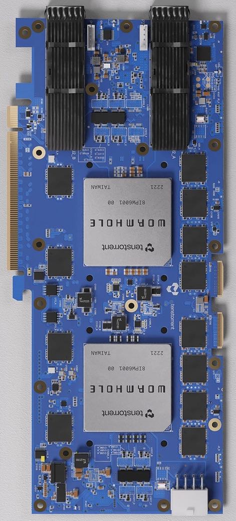 |  |
Each E tile can manage 100Gb ethernet, i.e. simultaneous transmit at 100Gb/s and receive at 100Gb/s. The 1st ASIC has E0 and E1 connected to one QSFP-DD cage, E6 and E7 connected to the other QSFP-DD cage, E8 and E9 connected to the 2nd ASIC, and E14 and E15 connected to a Warp 100 Bridge connector on the right. The other eight E tiles are not connected to anything on these particular boards. Meanwhile, the 2nd ASIC has E0 and E1 connected to the 1st ASIC, E6 and E7 connected to a Warp 100 Bridge connector on the right, and none of the other E tiles connected to anything.
The PCIe tile on the 2nd ASIC is similarly not connected to anything. There's a little SPI flash memory containing firmware and configuration for the ARC tiles, which can serve as an awkward communication channel: the 1st ASIC can write revised firmware/configuration to the flash, then trigger a board-level reset to cause both ARC tiles to re-load their firmware and configuration from the flash. Other than using tt-flash to occasionally update the firmware, and tt-topology to occasionally update the configuration, you likely won't be using this channel. That leaves ethernet as the primary means of communication between the two ASICs on the board, so to make any use of the 2nd ASIC, we're going to have to talk ethernet.
From the host, we can use the PCIe link to do whatever we want to the E8 / E9 tiles on the 1st ASIC, but until we've established ethernet communication, we have no way to affect the E0 / E1 tiles that they communicate with. Whatever we transmit from the E8 / E9 tiles will, at least initially, be received and processed by the base firmware on the E0 / E1 tiles. The details of that processing logic aren't necessarily documented by Tenstorrent, but the base firmware on the E8 / E9 tiles knows how to form and transmit ethernet packets that'll be received and understood by the base firmware on the E0 / E1 tiles. Hence we don't want to mess with the E8 / E9 tiles too much, as we'll need to ask the firmware on them to do our bidding. That means we'll need to understand the interface that the base firmware on the E8 / E9 tiles presents to the host. This interface isn't really documented either, but at least there are relevant header files. We start with a basic queue/ring structure:
struct eth_queue_t {
  uint32_t wr_req_counter;
  uint32_t wr_resp_counter;
  uint32_t rd_req_counter;
  uint32_t rd_resp_counter;
  uint32_t error_counter;
  uint32_t padding0[3]; // Aligns next field to 16 bytes
  uint32_t wr_idx;
  uint32_t padding1[3]; // Aligns next field to 16 bytes
  uint32_t rd_idx;
  uint32_t padding2[3]; // Aligns next field to 16 bytes
  routing_cmd_t contents[4];
};
Nothing too surprising in eth_queue_t; it starts with some counters that the base firmware increments in various scenarios, then wr_idx and rd_idx, and then space for four elements. The size of the queue, which is always between zero and four (inclusive), is given by (wr_idx - rd_idx) % 8. An empty queue will have wr_idx == rd_idx, whereas a full queue will have (wr_idx - rd_idx) % 8 == 4. To push on to the queue, assuming it isn't full, populate contents[wr_idx % 4] then do wr_idx = (wr_idx + 1) % 8. To pop from the queue, assuming it isn't empty, consume contents[rd_idx % 4] and then do rd_idx = (rd_idx + 1) % 8. Aside: the choice of % 8 is unfortunate; % 232 would have worked equally well, and % 232 is completely free on any 32-bit or 64-bit CPU (whereas % 8 is very cheap but not quite free).
Each element of the queue is an instance of the routing_cmd_t structure:
struct routing_cmd_t {
  uint32_t target_addr;
  uint16_t target_noc_xy; // From lo to hi: 4 bits zero, 6 bits NoC X, 6 bits NoC Y
  uint16_t target_shelf_xy; // From lo to hi: 6 bits shelf-level X, 6 bits shelf-level Y, 4 bits unused
  union {
    uint32_t inline_data;
    uint32_t data_block_length;
  };
  uint32_t flags;
  uint16_t target_rack_xy; // From lo to hi: 8 bits rack X (rack #), 8 bits rack Y (shelf #)
  uint16_t reserved[5];
  uint32_t data_block_dma_addr;
};

// Request flags:
#define CMD_WR_REQ         (1u << 0)
#define CMD_RD_REQ         (1u << 2)
#define CMD_DATA_BLOCK_DMA (1u << 4)
#define CMD_DATA_BLOCK     (1u << 6)
#define CMD_BROADCAST      (1u << 7)
#define CMD_USE_NOC1       (1u << 9)
#define CMD_TIMESTAMP      (1u << 10)
#define CMD_ORDERED        (1u << 12)

// Response flags:
#define CMD_WR_ACK                 (1u << 1)
#define CMD_RD_DATA                (1u << 3)
#define CMD_DATA_BLOCK_UNAVAILABLE (1u << 30)
#define CMD_DEST_UNREACHABLE       (1u << 31)
This structure requires slighly more explanation. A request will be either CMD_WR_REQ or CMD_RD_REQ, along with a bunch of optional flags. If we ignore the CMD_BROADCAST flag, these write requests and read requests target a particular location in the address space of a particular tile. The tile-local address is given in the target_addr field, and the tile in question is identified by a combination of the target_noc_xy and target_shelf_xy and target_rack_xy fields. That is, rather than using IPv4 or IPv6 addresses, a custom 6-dimensional addressing scheme is used. We already saw the NoC X and Y dimensions in part 1, noting that they are interleaved versus the actual physical placement of tiles, which is why (amongst other things) the right edge appears as the middle column and the bottom edge appears as the middle row:

If there are multiple Wormhole ASICs in a single server, then they too can be arranged into a logical grid, giving the shelf-level X and Y dimensions:

Finally, an aisle of server racks in a datacenter gives rack-level X (rack #) and Y (shelf #) dimensions:

That completes the detour describing the addressing scheme. Returning to the routing_cmd_t structure, the data to be written (for write requests) can either be a 4 byte value in inline_data, or a small block of data up to 1KB in size somewhere near the routing_cmd_t structure (set the CMD_DATA_BLOCK flag, put the length in data_block_length), or a large block of data up to 3.75GB in size sitting in host DRAM accessible via DMA (set both CMD_DATA_BLOCK and CMD_DATA_BLOCK_DMA, put the length in data_block_length, and the physical memory address in data_block_dma_addr - the kernel-mode driver can be used to obtain such addresses). For read requests, the options are similar: a 4 byte result can go directly in inline_data, or a small result up to 1KB in size can be written somewhere near the routing_cmd_t structure, or a large result up to 3.75GB in size can be written to host DRAM via DMA. The routing_cmd_t structure is used for responses as well as requests, though a different set of flags are applicable to responses, and the only interesting fields on responses are flags and inline_data. The high bits of response flags indicate errors, while the low four bits should contain either CMD_WR_ACK or CMD_RD_DATA. Everything is then wrapped up in a eth_base_firmware_queues_t structure:
struct eth_base_firmware_queues_t {
  uint64_t latency_counter[16];
  eth_queue_t sq; // Contains requests, for host -> E tile
  eth_queue_t reserved;
  eth_queue_t cq; // Contains responses, for E tile -> host
  char padding[4096 - sizeof(uint64_t)*16 - sizeof(eth_queue_t)*3];
  char buffers[4][1024];
};
Skipping over the latency_counter field, this contains a submission queue (sq), in to which the host pushes routing_cmd_t objects containing requests, and a completion queue (cq) from which the host pops routing_cmd_t objects containing responses. Each of the index fields has a single writer:
| Field | Writer | Readers |
|---|---|---|
sq.wr_idx | Host (as part of pushing) | Host, E tile |
sq.rd_idx | E tile (as part of popping) | Host, E tile |
cq.wr_idx | E tile (as part of pushing) | Host, E tile |
cq.rd_idx | Host (as part of popping) | Host, E tile |
The buffers field contains four 1KB buffers, used for requests or responses which have CMD_DATA_BLOCK set, but CMD_DATA_BLOCK_DMA unset. In such cases, request sq.contents[i] uses buffers[i], and response cq.contents[i] also uses buffers[i]. A little bit of care is required to ensure that a buffer isn't used by two different routing_cmd_t objects at once, but assuming that the queue indices start off aligned, and that every request generates a response, then the response to sq.contents[i] will end up in cq.contents[i], and at most one of these two things will require buffers[i].
Each E tile contains a single eth_base_firmware_queues_t structure in its SRAM, the address of which is stored at tile-local address 0x170. The host uses PCIe reads and writes to interact with this structure, and it is the responsibility of host software to avoid having multiple host threads interact with the same structure at the same time. The host can submit requests to read/write against any tile in the 6-dimensional space, and the base firmware on the E tile to which the request is submitted will do one of three things:
- If the target tile is the E tile itself, the request can be completed using RISC-V load/store instructions.
- Otherwise, if the target tile is on the same ASIC as the E tile, the request can be completed using NoC #0 (default) or NoC #1 (if
CMD_USE_NOC1is set). - Otherwise, the request can be forwarded to a different E tile; either to the E tile at the other end of the ethernet link, or to one of the other E tiles on the same ASIC. The receiving E tile will then do one of the same three things.
In the simple setup of a single n300s board, the rack # is 0, the shelf # is 0, and then the shelf-level coordinates are (0, 0) for the ASIC connected to PCIe and (1, 0) for the other ASIC. In more complex setups, tt-topology should be used to assign coordinates to ASICs.
Back in part 2, we obtained the value of RV_ADDR_NOC0_MC_DISABLE_COL on the 1st ASIC, thereby determining which rows were disabled. Knowing what we now know about ethernet tiles, we can obtain RV_ADDR_NOC0_MC_DISABLE_COL on both ASICs. To make things interesting, we'll have the host make a request to tile E10 at NoC coordinates (8, 6), but have the target of the request be RV_ADDR_NOC0_MC_DISABLE_COL on tile E2 at coordinates (8, 0). When targetting the 2nd ASIC, this'll require an ethernet hop between E8 and E0, as shown:

Continuing with the code from part 2, which deliberately eschews the useful software layers provided by Tenstorrent, we can start by obtaining the base firmware queues structure on tile (8, 6):
char* l1_tlb = set_tlb(dev, TLB_IDX_0, TLB_CFG_UNICAST(8, 6), 0);
uint32_t q_addr = *(volatile uint32_t*)(l1_tlb + 0x170);
eth_base_firmware_queues_t* q = (eth_base_firmware_queues_t*)(l1_tlb + q_addr);
We can then prepare the request for the base firmware, setting the target as RV_ADDR_NOC0_MC_DISABLE_COL on tile (8, 0):
routing_cmd_t c;
c.target_rack_xy = (0 << 0) + (0 << 8);
c.target_shelf_xy = (shelf_x << 0) + (shelf_y << 6);
c.target_noc_xy = (8 << 4) + (0 << 10);
c.target_addr = RV_ADDR_NOC0_MC_DISABLE_COL;
c.flags = CMD_RD_REQ;
Dispatching the command to the submission queue and reaping the result from the completion queue involves some grungy work:
void do_eth_cmd(eth_base_firmware_queues_t* q, routing_cmd_t* c) {
  // Spin while sq full
  uint32_t wr_idx = q->sq.wr_idx;
  uint32_t rd_idx;
  do {
    rd_idx = *(volatile uint32_t*)&q->sq.rd_idx;
  } while ((wr_idx - rd_idx) & 4u);

  // Push to sq
  routing_cmd_t* qc = q->sq.contents + (wr_idx & 3u);
  *(volatile __m256i*)qc = _mm256_loadu_si256((__m256i*)c);
  _mm_sfence();
  *(volatile uint32_t*)&q->sq.wr_idx = (wr_idx + 1) & 7u;

  // Spin while cq empty
  rd_idx = q->cq.rd_idx;
  do {
    wr_idx = *(volatile uint32_t*)&q->cq.wr_idx;
  } while (rd_idx == wr_idx);

  // Wait for cq entry to be populated
  qc = q->cq.contents + (rd_idx & 3u);
  do {
    _mm256_storeu_si256((__m256i*)c, *(volatile __m256i*)qc);
  } while (c->flags == 0);

  // Pop from cq
  *(volatile uint32_t*)&q->cq.rd_idx = (rd_idx + 1) & 7u;
}
One subtle point in the above is that the base firmware initially pushes an entry on to the completion queue with flags set to zero, and then populates the entry properly as a 2nd stage, so (somewhat unfortunately) two loops are required to pop from the completion queue.
We can then wrap all this up in some more loops:
for (uint32_t shelf_y = 0; shelf_y < 2; ++shelf_y) {
  for (uint32_t shelf_x = 0; shelf_x < 2; ++shelf_x) {
    routing_cmd_t c;
    c.target_rack_xy = (0 << 0) + (0 << 8);
    c.target_shelf_xy = (shelf_x << 0) + (shelf_y << 6);
    c.target_noc_xy = (8 << 4) + (0 << 10);
    c.target_addr = RV_ADDR_NOC0_MC_DISABLE_COL;
    c.flags = CMD_RD_REQ;
    do_eth_cmd(q, &c);
    printf("(%u, %u) -> ", shelf_x, shelf_y);
    if (c.flags == CMD_RD_DATA) {
      printf("value %u\n", c.inline_data);
    } else {
      printf("error %#08x\n", c.flags);
    }
  }
}
For my n300s board, the above prints:
(0, 0) -> value 3137
(1, 0) -> value 2121
(0, 1) -> error 0x80000008
(1, 1) -> error 0x80000008
There are CMD_DEST_UNREACHABLE errors for target_shelf_xy of (0, 1) and (1, 1), which makes sense. The value 3137 is what we already saw in part 2, and corresponds to bitmask 0b110001000001. The value 2121 is new, and tells us that the bitmask for the 2nd ASIC is 0b100001001001. This means that the 128 usable T tiles on my n300s board are at:

At this point we could use a routing_cmd_t to send new RISC-V code to the E tiles on the 2nd ASIC and have that code implement a communication protocol of our choosing rather than relying on the base firmware, but this blog post is long enough already, so it'll have to wait for another time. The complete code for this post consists of 201 lines, though half of that is unchanged from part 2. That wraps up part 4; if you're reading along, then part 5 is next.